


Brand: Neumann
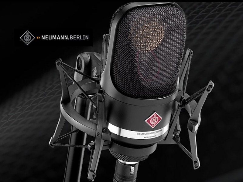
Neumann TLM 107
Category: Condenser Microphones
Large-Diaphragm Condenser Microphone • 5 Selectable Polar Patterns • 20 Hz–20 kHz Frequency Response • 10 dB-A Self-Noise • Up to 141 dB SPL
 Get 5% OFF on Prepaid Orders
Copied!
Get 5% OFF on your First Purchase.
Copied!
Buy 2 and GET 10% OFF
Copied!
Get 5% OFF on Prepaid Orders
Copied!
Get 5% OFF on your First Purchase.
Copied!
Buy 2 and GET 10% OFF
Copied!
GENERAL / TRANSDUCER TYPE
| SPECIFICATION | DETAILS |
|---|---|
| Acoustical Operating Principle | Pressure gradient transducer |
| Transducer Type | Large-diaphragm condenser |
| Capsule Design | Newly developed dual-diaphragm large-diaphragm condenser capsule, designed specifically for TLM 107 |
| Output Circuit | Transformerless (TLM series) solid-state FET circuit |
| Available Finishes | Nickel (standard) and matte black (bk) |
| Awards | TEC Award 2015; Best of Show Award, AES Convention 2013 |
POLAR PATTERN
| SPECIFICATION | DETAILS |
|---|---|
| Available Directional Patterns | Omnidirectional, Wide Cardioid, Cardioid, Hypercardioid, Figure-8 (5 patterns total) |
| Pattern Consistency | Consistent tonal balance maintained across all five polar patterns |
| Pattern Selection | Rear-panel navigation toggle with LED confirmation indicators |
FREQUENCY RESPONSE
| SPECIFICATION | DETAILS |
|---|---|
| Frequency Range | 20 Hz – 20 kHz |
| Frequency Response Consistency | Extended, carefully balanced response maintained in all five polar patterns |
| High-Pass Filter Settings | Lin (flat), 40 Hz, 100 Hz (three-position toggle) |
NOISE PERFORMANCE
| SPECIFICATION | DETAILS |
|---|---|
| Equivalent Noise Level (A-weighted, IEC 61672-1, RMS) | 10 dB-A |
| Equivalent Noise Level (CCIR, CCIR 468-3, quasi-peak) | 22 dB |
| Signal-to-Noise Ratio, A-weighted (re. 94 dB SPL, IEC 60268-1) | 84 dB |
| Signal-to-Noise Ratio, CCIR (re. 94 dB SPL, IEC 60268-1) | 72 dB |
| Dynamic Range (calculated: Max SPL − Self-Noise A-wtd) | 131 dB (141 − 10 = 131 dB) — confirmed by Neumann |
SPL HANDLING & PRE-ATTENUATION
| SPECIFICATION | DETAILS |
|---|---|
| Maximum SPL (THD 0.5%, pad off) | 141 dB SPL |
| Maximum SPL (THD < 0.5%, -6 dB pad) | 147 dB SPL |
| Maximum SPL (THD < 0.5%, -12 dB pad) | 153 dB SPL |
| Pad Settings Available | 0 dB (off), -6 dB, -12 dB (three-position toggle) |
| Distortion Reference | THD measured as equivalent electrical input signal (per Neumann specification note) |
SENSITIVITY & OUTPUT
| SPECIFICATION | DETAILS |
|---|---|
| Sensitivity at 1 kHz into 1 kΩ | 11 mV/Pa |
| Sensitivity (dBV/Pa, calculated) | −39.2 dBV/Pa (from 11 mV/Pa) |
| Maximum Output Voltage | 10 dBu |
| Rated Output Impedance | 50 Ω |
| Rated Load Impedance | 1000 Ω (minimum recommended load) |
| Output Connector | XLR 3F (3-pin female XLR, balanced) |
POWER REQUIREMENTS
| SPECIFICATION | DETAILS |
|---|---|
| Supply Voltage | 48 V ± 4 V (P48 phantom power, IEC 61938) |
| Current Consumption | 3.2 mA (from 48 V phantom supply) |
| Power Consumption (calculated) | 3.2 mA × 48 V ≈ 154 mW (within standard phantom power budgets) |
PHYSICAL SPECIFICATIONS
| SPECIFICATION | DETAILS |
|---|---|
| Weight | 445 g |
| Diameter | 64 mm |
| Length | 145 mm |
| Body Finish (nickel) | Nickel (warm silver) |
| Body Finish (black) | Matte black |
| Headgrille Design | Large tapered metal mesh headgrille, referencing the Neumann M 49 heritage design |
CONTROLS & INDICATORS
| SPECIFICATION | DETAILS |
|---|---|
| Polar Pattern Selection | Navigation toggle (rear), 5 positions: Omni / Wide Cardioid / Cardioid / Hypercardioid / Figure-8 |
| Pre-Attenuation (Pad) | Navigation toggle (rear), 3 positions: 0 dB / -6 dB / -12 dB |
| High-Pass Filter | Navigation toggle (rear), 3 positions: Lin / 40 Hz / 100 Hz |
| Status Indication | LED indicators adjacent to navigation toggle confirm selected polar pattern, pad and filter settings |
AVAILABLE VARIANTS & INCLUDED ACCESSORIES
| SPECIFICATION | DETAILS |
|---|---|
| TLM 107 (nickel) — Cat. No. 008666 | TLM 107 Microphone + SG 2 Swivel Mount + Wooden Presentation Box |
| TLM 107 bk (black) — Cat. No. 008667 | TLM 107 bk Microphone + SG 2 Swivel Mount + Wooden Presentation Box |
| TLM 107 Studio Set (nickel) — Cat. No. 008673 | TLM 107 Microphone + EA 4 Elastic Shock Mount (no wooden box) |
| TLM 107 bk Studio Set (black) — Cat. No. 008674 | TLM 107 bk Microphone + EA 4 bk Elastic Shock Mount (no wooden box) |
| Optional Accessories | EA 1 shock mount, PS 15 / PS 20 a pop screens, WS 47 windscreen, N 248 power supply, MNV 87 auditorium hanger, DS 120 double mount, IC 3 mt / IC 4 microphone cables, stand extensions STV 4/20/40/60, MF 3/4/5 table and floor stands, Z 26 mt shock mount |
COMPLIANCE & STANDARDS
| SPECIFICATION | DETAILS |
|---|---|
| Noise Weighting Standard | IEC 60268-1 (SNR reference); CCIR 468-3 quasi-peak (CCIR weighting); IEC 61672-1 RMS (A-weighting) |
| Phantom Power Standard | P48 IEC 61938 |
| Country of Manufacture | Germany (Georg Neumann GmbH, Berlin) |
| RoHS / Environmental | Subject to California Proposition 65 lead warning (as stated by Neumann) |
1. PRODUCT OVERVIEW
The Neumann TLM 107 is a large-diaphragm condenser studio microphone designed and manufactured by Georg Neumann GmbH, Berlin — the company universally regarded as the world's pre-eminent microphone maker. Sitting in the TLM (TransformerLess Microphone) series between the entry-level TLM 102 and the storied TLM 103, the TLM 107 was introduced to the market in 2013, earning the Best of Show Award at AES 2013 and the TEC Award in 2015. It fills a carefully considered niche: a microphone that delivers reference-class recording performance — with multiple polar patterns, flexible filtering, and exceptional dynamic range — at a price that brings it within reach of serious project and home studio owners as well as professional facilities.
The TLM 107 is built around a newly developed dual-diaphragm large-diaphragm capsule created specifically for this microphone, rather than being derived from a pre-existing design. This design decision allowed Neumann's engineers to optimise the capsule geometry, diaphragm material and polar-pattern switching behaviour as a unified system. The result is a microphone that, unusually for a large-diaphragm design, maintains a consistent tonal character across all five selectable polar patterns — omnidirectional, wide cardioid, cardioid, hypercardioid, and figure-8.
Underpinning the TLM 107's electronic architecture is the transformerless circuit topology that defines the entire TLM series. By eliminating the output transformer, Neumann achieves a signal path of extraordinary transparency: no transformer saturation, no low-frequency phase shift, and no restriction on bass transmission even at the highest signal levels. Self-noise measures 10 dB-A — among the quietest large-diaphragm microphones in production — while maximum SPL without pad reaches 141 dB SPL (at 0.5% THD), for a dynamic range of 131 dB. With the -12 dB pad engaged, maximum SPL rises to 153 dB.
The physical design deliberately echoes the silhouette of the M 49 tube microphone, with controls consolidated into a single navigation toggle on the rear of the body selecting among five polar patterns, three pad settings (0, -6, -12 dB) and three high-pass filter settings (flat, 40 Hz, 100 Hz). Available in nickel and matte black finishes, each offered standalone with an SG 2 swivel mount, or as a Studio Set with the EA 4 elastic shock mount.
2. CAPSULE TECHNOLOGY & TRANSDUCER ARCHITECTURE
The TLM 107's capsule is an entirely new design rather than an adaptation of a legacy element, engineered specifically to achieve consistent tonal behaviour across all five polar patterns — a technically significant ambition, since acoustic loading and diffraction effects on a capsule vary with frequency in ways unique to each polar pattern. The capsule geometry and diaphragm design were optimised computationally and empirically to minimise these pattern-dependent frequency response variations.
The result is that all five polar patterns exhibit the same carefully balanced extended high-frequency response and smooth low-frequency characteristics — quite extraordinary for a large-diaphragm microphone. An engineer can select the polar pattern appropriate to the acoustic environment without needing to re-equalise the channel or expect a change in the fundamental character of the recording.
The operating principle is that of a pressure gradient transducer, giving rise to the figure-8 base response from which other patterns are derived by adding omni (pressure) components. The large diaphragm area provides higher sensitivity and a more favourable signal-to-noise ratio than small-diaphragm capsules. Sensitivity is 11 mV/Pa (approximately -39 dBV/Pa), and the frequency range spans the full audible spectrum from 20 Hz to 20 kHz.
Outstanding transient response is a key design achievement of the capsule, governed by the ratio of diaphragm tension to diaphragm mass and by the mechanical compliance of the diaphragm mounting. A diaphragm with high tension relative to mass has a high resonant frequency, keeping mechanical behaviour across the entire audible range stiffness-controlled and highly linear.
3. FIVE SELECTABLE POLAR PATTERNS
The TLM 107 offers five polar patterns, selectable via the rear navigation toggle. Each pattern is suited to different recording situations, and the TLM 107's consistent tonal character across all five makes pattern selection a workflow decision rather than a sonic compromise.
3.1 Omnidirectional (Omni)
Captures sound equally from all directions with no proximity effect. Ideal for moving sources, room ambience capture, and preserving a space's natural acoustic. Preferred for orchestral room microphones and ambient beds.
3.2 Wide Cardioid
Extends the front pickup angle beyond standard cardioid, offering inclusive coverage of sources spread across a wider frontal arc without going to full omni. Retains moderate rear rejection and mild proximity effect — valuable for ensemble recording and acoustic guitar.
3.3 Cardioid
The most commonly used pattern and the TLM 107's most common deployment as a vocal microphone. Provides a heart-shaped pickup with approximately 25 dB of rejection at 180 degrees, with usable proximity effect and Neumann's characteristic extended, smooth high-frequency presence.
3.4 Hypercardioid
A narrower frontal pickup angle (~105 degrees at 3 dB down) with a small rear lobe of sensitivity at 180 degrees. Maximum rejection at approximately 110 degrees off-axis — effective for kick drum, close-miked loud amplifiers, and reverberant rooms.
3.5 Figure-8 (Bidirectional)
Captures sound equally front and rear while rejecting sources at 90 degrees from either side. Exhibits the strongest proximity effect of all patterns; used in M/S stereo recording, ribbon emulation, Blumlein pairs, and face-to-face interview setups.
4. TRANSFORMERLESS CIRCUITRY
The TLM designation defines a fundamental engineering philosophy at Neumann, introduced with the TLM 170 in 1983. The transformerless output stage replaces the traditional output transformer of FET-era designs with a direct-coupled solid-state circuit, removing several measurable artefacts: low-frequency high-pass behaviour from finite primary inductance, magnetic core saturation at high signal levels, and secondary high-frequency resonance from leakage inductance.
The TLM 107's transformerless output circuit eliminates all of these effects. Bass transmission is full and unrestricted even at the highest signal levels, because there is no primary inductance to impose a low-frequency roll-off. THD behaviour at high SPLs is governed by the electronic circuit rather than core saturation, resulting in a more linear and controllable distortion characteristic. The circuit achieves a low output impedance of 50 ohms, delivering excellent voltage damping and freedom from cable-capacitance or preamp-impedance level changes.
5. NOISE PERFORMANCE & DYNAMIC RANGE
The TLM 107 achieves a self-noise figure of 10 dB-A (A-weighted, per IEC 61672-1) and 22 dB CCIR (quasi-peak, per CCIR 468-3) — among the lowest available in a large-diaphragm condenser microphone at any price. A well-treated studio with HVAC off typically has a noise floor of 20–30 dB-A, meaning the room or the source — not the microphone — determines the noise floor in virtually all realistic recording scenarios.
Signal-to-noise ratio is specified as 84 dB (A-weighted, referenced to 94 dB SPL at 1 kHz) and 72 dB (CCIR-weighted, same reference). Dynamic range — the interval between the noise floor and the onset of distortion — is 131 dB (141 dB maximum SPL − 10 dB-A self-noise), placing the TLM 107 in the same dynamic range bracket as the finest studio recording chains, including top-tier 24-bit A/D converters.
6. SPL HANDLING & PRE-ATTENUATION (PAD)
Even without pad attenuation, the TLM 107 handles a maximum SPL of 141 dB (at 0.5% THD) — sufficient for close-miking percussion, brass, guitar amplifiers, and most loud acoustic sources. The -6 dB pad raises this ceiling to 147 dB, and the -12 dB pad extends it to 153 dB, approaching or exceeding any naturally occurring acoustic source except a jet engine or explosive detonation.
The pad is implemented as electronic pre-attenuation in the circuit, introducing no acoustic compromise such as altered directional patterns. Engaging the pad shifts the entire dynamic range window downward by 6 or 12 dB while the noise floor remains at 10 dB-A, increasing the effective dynamic range in context.
7. HIGH-PASS (LOW-CUT) FILTER SETTINGS
The TLM 107 offers three high-pass filter settings: flat (linear / no filtering), 40 Hz, and 100 Hz, switchable from the rear navigation toggle.
The 40 Hz filter attenuates subsonic content — stand-transmitted rumble, building vibration, HVAC infrasound — without affecting the musically meaningful bass content of most sources, and is also useful for reducing proximity-effect bass boost at close distances. For classical recording, broadcast, and most studio applications, 40 Hz provides a sensible hygiene filter that doesn't colour the source.
The 100 Hz filter is a more assertive intervention for pronounced proximity effect or environments with substantial low-frequency noise — common in project studios and location recording. At 100 Hz the filter begins to attenuate the musical bass range, so its use is situational: appropriate for spoken word, voiceover, and broadcast where intelligible midrange is the priority, and for drums and instruments where low-frequency clarity outweighs extended bass.
8. BUILD QUALITY & FORM FACTOR
Manufactured in Berlin to the standards of precision and longevity that have characterised Neumann microphones for nearly a century. The body is precision-machined metal with characteristic Neumann heft — a weight of 445 g confirms a substantial professional instrument. At 64 mm diameter and 145 mm length, the TLM 107 sits in the traditional large-body format, compatible with standard clips, boom arms, and shock mounts designed for the U 87 and comparable large-diaphragm designs.
The headgrille is a substantial metal mesh structure inspired by the M 49's design language, with a tapered profile from body to capsule housing that provides diffraction-free acoustic entry and contributes to the extended, smooth high-frequency response. Interior acoustic damping controls cavity resonances that can colour more abruptly-profiled designs.
The rear panel navigation toggle is a tactile, positive-action control cycling through patterns, pad, and filter settings, with LED indicators confirming the selected state at a glance even in dim lighting. Available in nickel (with SG 2 swivel mount, wooden presentation box) and matte black finishes, both acoustically and electronically identical; Studio Set versions substitute the EA 4 elastic suspension shock mount for enhanced vibration isolation.
9. IDEAL APPLICATIONS & USE CASES
The TLM 107's combination of very low self-noise, very high maximum SPL, five selectable polar patterns, and a consistently balanced tonal character across all patterns makes it exceptionally versatile:
- Lead Vocal Recording — cardioid's controlled proximity effect, extended presence, and low noise floor produce studio-standard realism across genres
- Acoustic Guitar — wide cardioid or cardioid captures full harmonic complexity without small-diaphragm edginess
- Piano — stereo pair in XY or Blumlein, or as a spot microphone over the strings
- Upright Bass — 40 Hz or 100 Hz filter tames low-frequency room modes while capturing full instrument body
- Drums — overhead recording in cardioid, hypercardioid, or figure-8; 141/153 dB SPL handling prevents capsule overload
- Percussion — congas, djembe, shakers benefit from outstanding transient response and high-peak handling
- Brass & Woodwinds — high SPL handling and transparent reproduction capture bite and body equally
- Guitar Amp Cabinet Close-Miking — cardioid or hypercardioid at close range with pad engaged
- Orchestral Recording — omni or wide cardioid stereo pairs as main microphones
- Choir & Ensemble Recording — omnidirectional pattern for natural, even pickup of large groups
- Broadcast & Radio — cardioid for single presenters; figure-8 for face-to-face interviews
- Voiceover, Narration & Audiobook Production — low noise and smooth HF response for intelligible recordings
- M/S Stereo Recording — figure-8 as the side (S) microphone paired with a cardioid mid (M)
- Room & Ambient Capture — omnidirectional at distance for acoustic beds and room prints
- Film & Broadcast Soundtrack Recording — extended dynamic range and consistent pattern behaviour for music-to-picture sessions
10. SPECIFICATION CROSS-VALIDATION AND MATHEMATICAL ANALYSIS
10.1 Dynamic Range Verification
Dynamic Range = Maximum SPL (THD 0.5%) − Equivalent Self-Noise (A-weighted)
Dynamic Range = 141 dB SPL − 10 dB-A = 131 dB
Neumann states a dynamic range of 131 dB. Confirmed exactly. ✓ VERIFIED.
10.2 Signal-to-Noise Ratio Verification
SNR (A-weighted) = 94 dB − 10 dB-A = 84 dB-A
SNR (CCIR) = 94 dB − 22 dB = 72 dB
Both figures confirmed exactly. ✓ VERIFIED.
10.3 Sensitivity in dBV/Pa
Sensitivity = 11 mV/Pa = 0.011 V/Pa
Sensitivity (dBV/Pa) = 20 × log₁₀(0.011) ≈ −39.2 dBV/Pa
Consistent with the typical range for large-diaphragm condensers (−35 to −45 dBV/Pa). ✓ CONSISTENT.
10.4 Pad Attenuation Verification
With −6 dB pad: 141 + 6 = 147 dB. Neumann specifies 147 dB. ✓ VERIFIED.
With −12 dB pad: 141 + 12 = 153 dB. Neumann specifies 153 dB. ✓ VERIFIED.
10.5 Effective Dynamic Range with Pad
Effective Dynamic Range (−6 dB pad) = 147 − 10 = 137 dB
Effective Dynamic Range (−12 dB pad) = 153 − 10 = 143 dB
The noise floor remains at 10 dB-A regardless of pad setting, since the pad is applied after the capsule's signal while self-noise persists at the same absolute level. The pad raises the distortion ceiling without lowering the noise floor. ✓ INTERNALLY CONSISTENT.
TECHNICAL SPECIFICATIONS AT A GLANCE
| SPECIFICATION | DETAILS |
|---|---|
| Type | Large-diaphragm condenser, dual-diaphragm capsule |
| Polar Patterns | Omni, Wide Cardioid, Cardioid, Hypercardioid, Figure-8 (5 total) |
| Frequency Range | 20 Hz – 20 kHz |
| Sensitivity | 11 mV/Pa (≈ −39 dBV/Pa) |
| Self-Noise | 10 dB-A (IEC 61672-1); 22 dB CCIR (CCIR 468-3) |
| Signal-to-Noise Ratio | 84 dB-A / 72 dB CCIR (ref. 94 dB SPL, 1 kHz) |
| Maximum SPL (no pad) | 141 dB SPL (0.5% THD) |
| Maximum SPL (−6 dB pad) | 147 dB SPL |
| Maximum SPL (−12 dB pad) | 153 dB SPL |
| Dynamic Range | 131 dB |
| Pad Settings | 0 dB, −6 dB, −12 dB |
| High-Pass Filter Settings | Flat, 40 Hz, 100 Hz |
| Output Impedance | 50 Ω (transformerless) |
| Rated Load Impedance | ≥ 1 kΩ |
| Weight | 445 g |
| Dimensions | 64 mm diameter × 145 mm length |
| Finishes | Nickel, Matte Black |
| Included Mount (Standard) | SG 2 swivel mount, wooden presentation box |
| Included Mount (Studio Set) | EA 4 elastic shock mount |
| Manufactured | Berlin, Germany |
| Awards | AES 2013 Best of Show, TEC Award 2015 |
HOW TO READ THIS DOCUMENT
This document is the operational companion to the Neumann TLM 107 Product Description & Technical Specifications reference. Where the specifications document answers "what does the TLM 107 do and how is it measured?", this document answers "how do I actually use the TLM 107 in my specific professional environment?" Each workflow section describes a concrete deployment scenario — physical microphone placement, signal routing, polar pattern selection, filter and pad settings, shock mounting practice, and the specific TLM 107 features that make the workflow efficient.
Each workflow section opens with a scenario description and then concludes with a Workflow Element table that functions as a practitioner's checklist — a quick reference card for engineers setting up the TLM 107 in that environment.
Three characteristics of the TLM 107 reappear as enabling advantages across every workflow in this document. First, the consistent tonal balance across all five polar patterns means pattern selection is a pure workflow decision — no re-equalising to compensate for a changed frequency response. Second, the 131 dB dynamic range (10 dB-A self-noise to 141 dB SPL maximum, extendable to 153 dB with the -12 dB pad) means the TLM 107 is genuinely usable from the quietest ambient recordings to the loudest close-miked percussion. Third, the transformerless circuit's transparency means the TLM 107 adds no electronic colouration of its own — it captures what is acoustically in front of it, preserving all processing options at the mix stage.
WORKFLOW 1 — THE PROFESSIONAL RECORDING STUDIO
Scenario A: Lead Vocal Recording in a Dedicated Vocal Booth
The professional recording studio vocal booth is the environment for which the TLM 107's core character — low self-noise, extended presence, controlled cardioid pattern, and transformerless transparency — is most directly optimised. The booth is typically 6 to 20 square metres with broadband acoustic treatment, leaving a decay time in the 100–300 ms range. The singer is positioned 15 to 40 cm from the microphone grille, slightly off-axis vertically (mouth aimed at the bottom third of the grille) to reduce plosive energy reaching the capsule directly.
The TLM 107 is mounted in the EA 4 elastic suspension shock mount (Studio Set version) to isolate it from stand-borne vibrations, footfalls, and low-frequency building resonances. The shock mount's suspension is tuned to attenuate below approximately 80 Hz, working alongside the TLM 107's 40 Hz high-pass filter to deliver a clean, vibration-free signal. A pop filter (Neumann PS 15 or PS 20 a, or fabric screen at 8–12 cm from the grille) protects against plosive burst pressure. Cardioid is set for maximum rear rejection of room reflections, and the pad stays at 0 dB since vocal SPLs rarely exceed 120 dB even at close range.
The output XLR routes to the studio patchbay and a high-quality preamp — typically discrete Class A or a high-headroom transformer-input design. Because the TLM 107's output impedance is only 50 Ω, it is immune to cable capacitance effects even on long runs (30 m or more). The 11 mV/Pa sensitivity means a preamp with 40–60 dB of gain is adequate for most vocal levels; the preamp's noise performance, not the TLM 107's, becomes the limiting factor in quiet passages.
Scenario B: Acoustic Instrument Recording with Polar Pattern Flexibility
For acoustic guitar, violin, cello, and similar instruments in the live room, the TLM 107's five polar patterns provide genuine operational flexibility. For a single acoustic guitar, cardioid at 30–50 cm from the 12th fret, angled slightly toward the soundhole, captures a full, balanced tone. For a player who moves or shifts weight, switching to wide cardioid relaxes the pickup angle. For a room with excellent natural acoustics, omni at 1–2 m from the instrument captures it in the context of its space — particularly effective for classical guitar and folk recordings.
Workflow 1A Checklist — Lead Vocal Recording
| WORKFLOW ELEMENT | DETAILS / CONFIGURATION |
|---|---|
| Microphone Mount | EA 4 elastic suspension shock mount (Studio Set); mounted on heavy-duty boom arm |
| Polar Pattern | Cardioid |
| Pad Setting | 0 dB (standard vocal SPLs do not require attenuation) |
| High-Pass Filter | 40 Hz (removes subsonic content and stand vibration; preserves all musically relevant bass) |
| Microphone Distance | 15–40 cm from singer's mouth; slight downward angle to reduce plosives |
| Pop Filter | PS 15 or PS 20 a placed 8–12 cm from headgrille; fabric screen at comparable distance also appropriate |
| Cable Routing | Balanced XLR from microphone → patchbay → microphone preamplifier input |
| Preamp Gain | 40–60 dB typical; increase for quieter voices in head voice or falsetto passages |
| Acoustic Environment | Treated vocal booth; T60 approximately 100–300 ms; no HVAC during recording |
| Session Monitoring | DAW input monitoring disabled during takes; headphone cue mix at comfortable level; match latency to DAW buffer |
Workflow 1B Checklist — Acoustic Instrument Recording
| WORKFLOW ELEMENT | DETAILS / CONFIGURATION |
|---|---|
| Polar Pattern | Cardioid (single instrument, controlled room); Wide Cardioid (larger instrument or moving player); Omni (room ambience desired) |
| Pad Setting | 0 dB (acoustic instruments); -6 dB if guitar body resonance or loud strumming causes overload |
| High-Pass Filter | 40 Hz (typical); Lin if extended bass response of instrument is critical (e.g., upright bass body) |
| Microphone Position (guitar) | 30–50 cm from 12th fret, angled toward soundhole at approximately 30–45 degrees |
| Microphone Position (piano) | 30–60 cm above strings, lid open, aimed at mid-register strings; stereo pair for full piano |
| Shock Mount | EA 4 or EA 1; floor stand vibration isolation particularly important in live room recordings |
| Proximity Effect Management | At distances greater than 30 cm, proximity effect is minimal; engage 40 Hz filter if recording at very close range in cardioid |
WORKFLOW 2 — HOME STUDIO & PROJECT STUDIO
Scenario: Achieving Professional Results in Acoustically Imperfect Environments
The home and project studio present challenges the TLM 107's specifications are specifically well-suited to address: untreated or partially treated acoustics, variable external noise, limited preamp quality, and no dedicated isolation booth. The TLM 107's 10 dB-A self-noise — lower than the ambient noise of even a fairly quiet domestic room — means the microphone itself does not impose a noise floor problem. The real challenge is managing room reflections and external noise ingress.
In an untreated room, cardioid's approximately 25 dB of rear rejection significantly reduces the contribution of a rear wall reflection. Positioning the microphone so its null point (180°) faces the most problematic reflective surface is the first and most important decision. Portable reflection filters placed behind the grille can further reduce early reflections, particularly for vocal recording.
For computer-based recording, the primary noise concern beyond room acoustics is computer fan noise. The hypercardioid pattern's narrow frontal capture angle, with the microphone's side facing the computer, places the fan noise near the pattern's maximum rejection angle — a practical "null steering" technique. Alternatively, the 100 Hz high-pass filter, while too aggressive for most musical recording, works well for spoken word, voiceover, and podcast recording in rooms with low-frequency traffic noise.
Workflow 2 Checklist — Home & Project Studio
| WORKFLOW ELEMENT | DETAILS / CONFIGURATION |
|---|---|
| Room Treatment Strategy | Bass trap in corners; broadband absorption on first reflection points (side walls, ceiling) |
| Polar Pattern | Cardioid (most situations); Hypercardioid if directional noise rejection is required |
| Null Point Orientation | Rear null (180° cardioid) or side null (~110° hypercardioid) faces primary noise source or hard reflective surface |
| Pad Setting | 0 dB for vocals and acoustic instruments; -6 dB if electric guitar amplifier is in the same room |
| High-Pass Filter | 40 Hz (standard); 100 Hz for voiceover in rooms with external traffic noise or HVAC rumble |
| Shock Mount | EA 4 strongly recommended; home studio floors transmit significant vibration from foot traffic and HVAC |
| Computer Fan Noise | Use hypercardioid with side facing computer, or relocate computer outside the recording space |
| Pop Protection | Pop screen mandatory at home studio distances (10–25 cm) where precise position control is difficult |
| Cable Quality | Balanced XLR; minimum 6 metres if audio interface is outside the recording area to reduce computer fan noise pickup |
WORKFLOW 3 — BROADCAST & RADIO STUDIO
Scenario A: Single-Presenter Radio or Podcast Studio
The broadcast studio demands a microphone that delivers consistently intelligible, broadcast-ready voice quality with minimal engineering intervention. The TLM 107 in cardioid meets this requirement fully. It's typically mounted on a desk arm (Neumann MF 3 or a broadcast arm such as the Yellowtec M!ka) with the EA 4 shock mount, positioned 15–25 cm from the presenter's mouth at approximately mouth height, tilted 10–15 degrees toward the presenter to exploit the slight presence lift of the on-axis cardioid response. The 100 Hz high-pass filter is standard in broadcast, where extended bass creates boominess and reduces intelligibility on air.
The transformerless output circuit is particularly valued in broadcast installations, where the signal may travel long cable runs to a remote console or IP audio network interface. The 50 Ω output impedance ensures cable capacitance on runs up to 100 metres introduces negligible high-frequency loss. Low self-noise also benefits broadcast, where studios are not perfectly silent — a microphone with higher self-noise would compound the existing background floor.
Scenario B: Two-Presenter Face-to-Face Format Using Figure-8
For interview formats where two presenters face each other across a small table, a single TLM 107 in figure-8 captures both voices simultaneously. The microphone is positioned at the midpoint, with front and rear capsule faces aimed at each presenter. Null points at 90 degrees reject the sides of the table, reducing pickup of laptop keyboards, handling noise, or off-axis reflections. This single-microphone technique reduces installation cost and complexity, eliminates phase cancellation risk between two closely spaced cardioids, and produces a natural, balanced representation of both voices.
Workflow 3A Checklist — Single-Presenter Broadcast
| WORKFLOW ELEMENT | DETAILS / CONFIGURATION |
|---|---|
| Polar Pattern | Cardioid |
| Pad Setting | 0 dB (broadcast vocal SPLs are well below 141 dB maximum) |
| High-Pass Filter | 100 Hz (standard broadcast setting for intelligibility and anti-boom) |
| Microphone Mount | EA 4 on broadcast desk arm (Neumann MF 3 or third-party); desk arm isolates from desk impacts |
| Microphone Position | 15–25 cm from mouth; slight upward tilt (microphone below mouth line) to reduce plosives and sibilance |
| Signal Routing | XLR → broadcast console mic input (AES67/DANTE network interface if IP-based studio) |
| Preamp Gain | 40–50 dB typical for broadcaster at 20 cm distance |
| Monitoring | Closed-back headphones for presenter; console operator monitors on studio monitors |
Workflow 3B Checklist — Two-Presenter Figure-8 Configuration
| WORKFLOW ELEMENT | DETAILS / CONFIGURATION |
|---|---|
| Polar Pattern | Figure-8 |
| Microphone Position | Centred between two presenters at equal distance (approximately 25–40 cm per presenter) |
| Null Point Orientation | Null at 90° and 270° faces sides of table; away from laptops, sound-making surfaces |
| Pad Setting | 0 dB |
| High-Pass Filter | 100 Hz (both voices benefit from bass reduction in close-to-table broadcast setting) |
| Proximity Effect | Figure-8 has strong proximity effect; presenters should maintain consistent distance to avoid level and tonal inconsistency |
| Pop Protection | Pop screen or proximity pop filter at each presenter face; figure-8 is sensitive to plosives from both front and rear |
| Microphone Stand | Desk arm centred between two presenter positions; height allows microphone to be level with or just above desk surface |
WORKFLOW 4 — VOICEOVER, NARRATION & ADR (AUTOMATED DIALOGUE REPLACEMENT)
Scenario: Voiceover Booth or ADR Stage with Post-Production Chain
Voiceover and narration recording places a very high premium on clarity, intelligibility, and freedom from colouration: the recorded voice must survive heavy post-production processing without revealing any artefacts from the recording chain. The TLM 107's transformerless circuit and outstanding transient response make it highly suitable — it captures consonants and fricatives with precision and without edginess, an important quality for long-form narration where listener fatigue is a consideration.
For ADR, the re-recorded voice must match the spectral character of the original location recording, or be precise enough for the ADR editor to equalise into conformity with production dialogue. The TLM 107's flat, extended response provides the best possible starting point for this matching work. The ADR stage also demands very low self-noise so the re-recorded dialogue can sit cleanly under music and effects at low levels — a requirement the 10 dB-A noise floor satisfies fully.
In an ADR session, the microphone is typically positioned 30–50 cm from the actor's mouth in cardioid, with the actor facing the screen and the microphone positioned above or below the sight line, depending on studio layout. A large-diameter pop filter at 12–15 cm from the grille protects against burst plosives without restricting movement. The 40 Hz high-pass filter removes any floor vibration (film mixing stages are not always perfectly isolated), and the 0 dB pad is appropriate for all normal dialogue levels.
Workflow 4 Checklist — Voiceover, Narration & ADR
| WORKFLOW ELEMENT | DETAILS / CONFIGURATION |
|---|---|
| Polar Pattern | Cardioid (standard for all VO and ADR work) |
| Pad Setting | 0 dB (standard dialogue SPLs are well below 141 dB ceiling) |
| High-Pass Filter | 40 Hz (removes floor vibration without affecting voice fundamental); 100 Hz for broadcast delivery in reverberant booths |
| Microphone Position (VO) | 20–40 cm from talent's mouth; microphone at slight downward angle to reduce plosives |
| Microphone Position (ADR) | 30–50 cm; positioned to avoid blocking talent's view of picture playback screen |
| Pop Screen | PS 15 or PS 20 a at 12–15 cm from grille; large diameter provides good coverage for talent movement |
| Shock Mount | EA 4 mandatory on film ADR stages where floor vibration from projection equipment is a risk |
| Signal Routing | XLR → microphone preamplifier → ADR workstation (Pro Tools or similar DAW); sync to picture via LTC timecode reader |
| Monitoring for Talent | Headphone cue: pre-roll with guide track; actor hears previous production dialogue in one ear, their own live ADR in the other |
| Post-Processing Chain | High-pass at 80–100 Hz; de-esser at 5–8 kHz; compressor (3:1, fast attack, medium release); EQ to match production dialogue spectrum |
WORKFLOW 5 — PODCAST & STREAMING PRODUCTION
Scenario: Multi-Host Podcast Studio with Remote Guest Integration
The professional podcast studio has evolved into a full media production environment supporting video streaming, real-time audience interaction, and simultaneous recording to multiple platforms. Here, the TLM 107 performs as a professional vocal microphone that is also visually appropriate for an on-screen format: its Neumann heritage, distinctive headgrille design, and available matte black finish (which photographs exceptionally well on camera) contribute to the premium aesthetic of a professional podcast production.
In a multi-host setup with two to four hosts, each host should have their own dedicated TLM 107 rather than sharing a figure-8 microphone — individual microphones allow independent gain, processing, and noise-gate settings per host, and separate channels for post-production editing. Each is set to cardioid, with the polar null aimed at the neighbouring host's microphone to maximise isolation. The 100 Hz high-pass filter is engaged for all hosts for broadcast-appropriate spectral content, and the EA 4 shock mount isolates desk noise from table impacts. The 0 dB pad is appropriate; podcast vocal levels are well below the TLM 107's maximum SPL.
Remote guests connected via audio-over-IP (Cleanfeed, Source Connect, Riverside.fm or Zoom) are received at the console and fed back to each host via headphone cue mixes. The TLM 107's low self-noise matters here: at quiet moments when one host is listening to a remote guest, the local microphone channel is technically open, and any self-noise is present in the listening environment. At 10 dB-A, this noise is below the threshold of audibility in normal monitoring, so the podcast's overall perceived quality is not degraded during dialogue pauses.
Workflow 5 Checklist — Podcast & Streaming Production
| WORKFLOW ELEMENT | DETAILS / CONFIGURATION |
|---|---|
| Polar Pattern | Cardioid (each host's microphone independently) |
| Pad Setting | 0 dB |
| High-Pass Filter | 100 Hz (broadcast-appropriate vocal spectral content; reduces desk rumble and low-frequency noise) |
| Microphone Placement per Host | 15–25 cm from mouth; desk arm or short boom; avoid blocking camera sight line if video recording |
| Shock Mount | EA 4 on each microphone; essential for desk noise isolation in a discussion/interview format |
| Polar Null Orientation | Each cardioid microphone's rear null aimed at adjacent host microphone positions to maximise channel isolation |
| Interface/Console | Minimum one input channel per host; each channel independently gated, compressed and EQ'd |
| Remote Guest Audio | Received via audio-over-IP tool (Cleanfeed / Source-Connect / Riverside.fm); mixed to host headphone cues |
| DAW Recording | Each host on separate track; remote guest on separate track; all tracks recorded simultaneously to DAW |
| Streaming | DAW or hardware mixer output routed to streaming encoder (OBS, Ecamm, StreamYard); separate mix for stream vs. podcast master |
| Post-Production | Individual track editing; de-essing at 5–8 kHz; multiband compression; noise gate to reduce bleed between hosts |
WORKFLOW 6 — DRUM & PERCUSSION RECORDING
Scenario A: Overhead Microphone Pair for Full Drum Kit
Drum overhead recording exploits two of the TLM 107's most important characteristics: exceptional SPL handling (141 dB without pad, extendable to 153 dB with -12 dB pad) and extended transient response. Overhead microphones are exposed to SPL levels that would overload many large-diaphragm microphones, particularly at close distances over a hard-hitting drummer. The 141 dB maximum SPL at 0 dB pad is sufficient for most studio overhead positions (typically 60–100 cm above the kit), but the -6 dB pad provides additional headroom insurance for very close overheads or extremely loud players.
As a stereo overhead pair, two TLM 107 microphones in cardioid are the standard configuration — XY coincident, ORTF (17 cm spacing, 110° included angle), or a simple spaced pair over the left and right sides of the kit. Cardioid's consistent frequency response across the entire kit radius ensures cymbals, snare, and toms are all captured with the same spectral character rather than the off-axis colouration that affects microphones with inconsistent polar patterns. The 40 Hz high-pass filter eliminates sub-bass bleed from the bass drum into the overhead capsules — energy that adds nothing to the overhead image and requires extensive EQ during mixing if left unchecked.
Scenario B: Kick Drum or Snare Spot Microphone
For spot miking individual drums at close range, the hypercardioid pattern combined with the -6 or -12 dB pad creates a highly capable close-miking tool. The narrow frontal acceptance angle reduces bleed from adjacent drums and cymbals — the central challenge of individual spot miking. The -6 dB pad (147 dB ceiling) or -12 dB pad (153 dB) are both appropriate at the close range and high SPL of a snare or kick drum position. The outstanding transient response preserves the sharp attack of each stick hit, providing the transient detail that makes a recorded drum sound punchy and well-defined in a dense mix.
Workflow 6A Checklist — Drum Overhead Pair
| WORKFLOW ELEMENT | DETAILS / CONFIGURATION |
|---|---|
| Polar Pattern | Cardioid (both microphones of the stereo pair) |
| Pad Setting | 0 dB (standard overhead position, 60–100 cm above kit); -6 dB for very close overhead position (under 40 cm) or extremely loud drummer |
| High-Pass Filter | 40 Hz (removes sub-bass bleed from kick drum without affecting cymbal or tonal drum content) |
| Stereo Configuration | XY coincident (0 cm spacing, 90° cardioid angle) OR ORTF (17 cm spacing, 110° included angle, 30 cm above kit) OR spaced pair (1–1.5 m above kit) |
| Microphone Height | 60–100 cm above snare for full-kit XY or ORTF; 150–200 cm for distant room-blend overhead position |
| Shock Mount | EA 4 or EA 1; overhead boom arm vibration transmitted from kit stand through floor is minimal but present |
| Preamp Gain | 20–40 dB typical; overhead levels are relatively high due to proximity and drum SPL |
| Phase Coherence | Both microphones of the pair must be time-aligned (match cable lengths or use DAW sample-level delay adjustment) |
Workflow 6B Checklist — Close-Miked Snare or Kick
| WORKFLOW ELEMENT | DETAILS / CONFIGURATION |
|---|---|
| Polar Pattern | Hypercardioid (maximum rejection of adjacent drum bleed) |
| Pad Setting | -6 dB (snare at 10–20 cm); -12 dB (kick drum inside the drum or at beater head) |
| High-Pass Filter | 40 Hz (snare); Lin (kick drum — preserve sub-bass fundamental) |
| Microphone Distance | 10–25 cm from snare head, aimed at centre; 20–40 cm inside or at port of kick drum |
| Null Point Orientation | Hypercardioid side nulls (~110°) aimed at hi-hat and floor tom to maximise bleed rejection |
| Mount | Short boom arm with heavy base or clip-on adapter for drum shell mounting; EA 4 for isolation from mechanical drum vibration |
WORKFLOW 7 — ORCHESTRAL & CLASSICAL MUSIC RECORDING
Scenario: Main Microphone Array in a Concert Hall or Rehearsal Room
Classical music recording makes the most demanding possible requirements of a microphone: the dynamic range of a full symphony orchestra spans from near-inaudible pianissimo strings to fortissimo brass and percussion well exceeding 100 dB SPL, all captured with complete fidelity on a single microphone position or small array. The TLM 107's 131 dB dynamic range (10 dB-A noise floor to 141 dB SPL) is well-matched. A large symphony orchestra produces peaks of 110–120 dB SPL at the main microphone position (typically 6–15 m from the ensemble front), and the TLM 107 handles these with 21–31 dB of headroom to spare at 0 dB pad.
The omnidirectional pattern is the classical recordist's preferred choice for main-pair microphones in a good acoustic, because omni captures the full acoustic of the hall — early reflections that give the hall its sense of size, and the late reverberant tail that defines its character — without proximity effect or rear rejection. Two TLM 107 microphones in omni, spaced 40–100 cm apart in an AB configuration at the listening position (typically 6–12 m from the stage front, 3–4 m above the floor), form the classic AB omni main pair.
Alternatively, for a Decca Tree configuration — the most widely used main array in classical recording — three TLM 107 microphones are used: two in omni spaced approximately 2 m apart left and right, and one in the centre (cardioid or omni) mounted 1 m forward of the left-right pair. Pioneered by the Decca engineering team for London recordings in the 1950s and 1960s, this array produces a stable, natural stereo image with good depth and hall perspective. The TLM 107's matching capsule character across all five patterns ensures the three microphones produce a consistent spectral character regardless of which pattern each is using.
Workflow 7 Checklist — Orchestral Main Pair
| WORKFLOW ELEMENT | DETAILS / CONFIGURATION |
|---|---|
| Polar Pattern | Omnidirectional (AB main pair or Decca Tree outer mics); Cardioid or Omni (Decca Tree centre) |
| Pad Setting | 0 dB (concert hall main position: 6–15 m from ensemble; peaks 110–120 dB SPL well within 141 dB limit) |
| High-Pass Filter | Lin (flat) — preserve the full low-frequency response of hall and ensemble; no proximity effect in omni to counteract |
| Microphone Spacing (AB Pair) | 40–100 cm between two omni microphones; closer for chamber ensemble, wider for full orchestra |
| Decca Tree Spacing | Left and right: 2 m apart; centre: 1 m forward of L/R midpoint; all microphones at equal height |
| Microphone Height | 3–4 m above floor; suspended from ceiling-mounted poles or orchestra bar; use MNV 87 auditorium hangers if available |
| Shock Mount | EA 4 or Z 26 mt; suspension hangers provide inherent vibration isolation in overhead positions |
| Outfill Microphones | Additional cardioid or wide cardioid TLM 107 microphones can serve as outriggers (left/right extremes) to widen the stereo field for very large ensembles |
| Signal Routing | XLR to multitrack recorder (stereo master or multichannel DAW); reference monitoring in control room during session |
| Recording Level | Target -18 to -12 dBFS peak for classical recording; leave at least 12 dB of digital headroom above the expected peak level |
WORKFLOW 8 — M/S STEREO RECORDING
Scenario: Mid-Side Array Using Two TLM 107 Microphones
Mid-Side (M/S) is a coincident stereo technique in which one microphone captures the mono centre image (Mid, M) and a second in figure-8 captures the lateral differences (Side, S). The decoded stereo signal is obtained by summing and differencing: Left = M + S, Right = M − S. M/S's critical advantage over XY or ORTF is that stereo width is variable in post-production by adjusting the M-to-S level ratio — a wider S contribution creates a wider image, and setting S to zero produces a pure mono signal that is fully mono-compatible. The TLM 107's figure-8 pattern makes it the ideal Side microphone, and its cardioid or hypercardioid patterns serve equally well as the Mid.
In a two-TLM-107 M/S array, both microphones are mounted as close as possible to coincident (capsules vertically aligned) on a stereo bar or stacked mount. The Mid is set to cardioid (or wide cardioid for a broader centre), and the Side to figure-8 with its null points aimed at the Mid microphone's on-axis direction. Both microphones' filters are set to the same position (typically flat or 40 Hz depending on the source), and pad settings should match unless there's a specific level difference between channels requiring independent adjustment.
The TLM 107's consistent tonal balance across patterns is particularly important in M/S recording because the Mid and Side signals are processed together, and any spectral mismatch would produce tonal inconsistencies in the decoded stereo image. Because the capsule design explicitly addresses this cross-pattern consistency, a stereo pair of TLM 107 microphones produces an M/S array with an unusually coherent spectral character across both channels.
Workflow 8 Checklist — M/S Stereo Array
| WORKFLOW ELEMENT | DETAILS / CONFIGURATION |
|---|---|
| Mid Microphone Pattern | Cardioid (standard); Wide Cardioid (broader centre image); Hypercardioid (narrower, more focused centre image) |
| Side Microphone Pattern | Figure-8 (mandatory for S component in M/S) |
| Physical Array | Both microphones stacked vertically (Side above Mid, or Mid above Side); capsules as close as possible (coincident ideal) |
| Null Orientation (Side) | Figure-8 null points (90° and 270°) aimed along the Mid microphone's on-axis direction (front-rear axis of the array) |
| Pad Settings | Match both microphones unless SPL difference between M and S channels requires independent adjustment |
| Filter Settings | Match both microphones (both Flat, or both 40 Hz) |
| M/S Decoding | In DAW: duplicate Side channel; invert polarity on duplicate; route Mid+Side to Left, Mid−Side to Right; width adjusted by Side level trim |
| Width Control | Higher Side level = wider stereo image; Side = 0 = pure mono centre; width adjustable non-destructively in post-production |
| Mono Compatibility | M/S decoded stereo sums to perfect mono when L+R are summed (Side cancels perfectly); superior mono compatibility vs. XY or spaced pairs |
WORKFLOW 9 — FILM & DOCUMENTARY AUDIO (CONTROLLED PRODUCTION ENVIRONMENT)
Scenario: Dialogue Recording on a Controlled Shoot with Overhead Boom
On a film or television drama shoot conducted in a controlled studio or location environment — as opposed to documentary-style run-and-gun production — the TLM 107 is a capable boom microphone for intimate dialogue recording, set piece scenes, and any situation where a large-diaphragm condenser can be positioned on a boom pole with adequate clearance above the frame line. The primary requirement is a tight polar pattern that rejects the acoustic of the shooting environment while capturing close voices clearly. Both the cardioid and hypercardioid patterns serve this application.
On a quiet or studio-built set, cardioid captures dialogue with the spacious, natural quality of a properly characterised large-diaphragm capsule. In a more reverberant or noisy environment, hypercardioid's narrower acceptance angle reduces room pickup and allows the boom operator to work at a slightly greater distance while maintaining adequate direct-to-reverberant ratio. The 100 Hz high-pass filter is typically engaged for all dialogue recording to address low-frequency ambience, clothing rustle, and boom pole vibration — though the EA 4 shock mount remains essential for isolating grip-induced vibration.
For music documentary, concert film, and live performance film recording, where the TLM 107 serves as a spot microphone for individual instruments or an ambient room microphone for audience and hall atmosphere, the full range of polar patterns becomes relevant. As a room atmosphere microphone, the omnidirectional pattern at distance captures the natural reverberation and audience presence that gives a concert film its sense of being "in the room." The very low self-noise is important here, as room atmosphere microphones are frequently recorded at lower levels than spot microphones and require significant gain, which amplifies any self-noise proportionally.
Workflow 9 Checklist — Film Dialogue Boom (Controlled Production)
| WORKFLOW ELEMENT | DETAILS / CONFIGURATION |
|---|---|
| Polar Pattern | Cardioid (controlled studio set, quiet environment); Hypercardioid (reverberant or noisy location) |
| Pad Setting | 0 dB (normal dialogue levels) |
| High-Pass Filter | 100 Hz (standard for film dialogue; removes low-frequency ambience and boom pole vibration) |
| Boom Mount | EA 4 shock mount on boom pole; boom pole rubber grip tape to reduce handling noise transmission |
| Boom Position | Above frame line, angled downward toward talent mouth at 45–60 degrees; distance 40–80 cm |
| Timecode | If recording to separate audio recorder, sync to production video via LTC timecode on a dedicated audio channel; jam sync before each take |
| Signal Routing | XLR boom cable → sound bag mixer/recorder (e.g., Sound Devices 633/MixPre series) → multitrack WAV files; timecode embedded |
| Monitoring | Sound mixer monitors via headphones (Sony MDR-7506 or similar) on boom channel; boom operator receives headphone feed |
| Wind Protection (exterior) | WS 47 windscreen for exterior shoots; replace with blimp/zeppelin system for windy exterior conditions |
WORKFLOW 10 — EDUCATIONAL & ACADEMIC AUDIO FACILITIES
Scenario: University Recording Studio or Music College Teaching Studio
University music schools, audio engineering programmes, and conservatoires are increasingly equipping teaching studios with professional-standard microphones rather than the entry-level instruments common in earlier decades. This reflects the recognition that students who learn on professional equipment are better prepared for industry practice, and that teaching microphone technique — polar pattern selection, proximity effect management, transient response — is impossible with microphones that don't properly exhibit these characteristics. The TLM 107 is an ideal teaching microphone because it makes the consequences of every technical decision clearly audible.
The five polar patterns allow a single microphone to demonstrate the full range of directional recording techniques in one session: the instructor can switch from omni (natural room sound, absence of proximity effect) to cardioid (directional control, proximity effect onset) to figure-8 (bidirectional capture, null-point rejection) to hypercardioid (close-miking SPL handling, maximum side rejection) in real time, with students hearing the consequences of each choice without introducing any other variable. The consistent tonal character across all patterns means the differences students hear are genuinely attributable to the acoustic physics of the polar pattern, not to an inconsistent capsule design.
For practical recording sessions, the TLM 107 serves as a reference-quality vocal and instrument microphone that places no ceiling on students' ability to achieve professional results. A student recording with the TLM 107 and a quality preamp can produce a signal chain that is, in every measurable sense, equal to a professional studio's — removing the equipment quality variable from the assessment and ensuring the grade reflects the student's decisions rather than the equipment's limitations.
Workflow 10 Checklist — Educational Recording Studio
| WORKFLOW ELEMENT | DETAILS / CONFIGURATION |
|---|---|
| Primary Teaching Application | Demonstration of polar pattern selection, proximity effect, filter and pad operation; reference vocal and instrument recording for student assignments |
| Polar Pattern (Teaching) | All five patterns; switch during demonstrations to illustrate acoustic differences |
| Polar Pattern (Student Recording) | Cardioid (default); pattern selection determined by student as part of assignment brief |
| Pad Setting (Teaching) | Demonstrate 0, -6, and -12 dB settings with a high-SPL source (drums or amplifier) to illustrate SPL handling |
| Pad Setting (Recording) | 0 dB for vocals and standard instruments; -6 dB for drums, brass or loud guitar amplifiers |
| High-Pass Filter (Teaching) | Demonstrate Lin vs. 40 Hz vs. 100 Hz on a vocal or close-miked guitar to illustrate proximity effect and filter response |
| Mount | EA 4 standard; demonstrate the difference between EA 4 isolation and standard clip for vibration isolation lesson |
| Studio Installation | Patchbay connection to multiple preamplifier options (e.g., transparent solid-state, transformer-input, high-gain console strip) to demonstrate preamp influence on TLM 107 output |
| Assessment Use | Student vocal and instrument recordings submitted as assessed files; TLM 107 ensures all students work from the same reference quality starting point |
WORKFLOW 11 — ROOM & AMBIENT MICROPHONE
Scenario: Room Microphone for Drums, Strings, or Ensemble
The room microphone is one of the most powerful tools in a recording engineer's palette. Used at distances of 2 to 10 metres from the source in an acoustically interesting room, it captures the sound of the space itself — the early reflections that give music its sense of physical location, and the late reverb tail that extends the sustain of each note. Blended with close microphones, the room signal adds dimension, air, and naturalness that no digital reverb processor can convincingly replicate.
The omnidirectional pattern is the first choice for room microphone applications, because omni captures the room equally from all directions and produces a spacious, three-dimensional image that no directional microphone can match. The absence of proximity effect means the room microphone does not colour the bass with pattern-dependent boost, allowing the room's natural acoustic character to be captured faithfully. The 10 dB-A self-noise matters particularly here — at distance from the source, lower signal levels amplify any self-noise proportionally, and the TLM 107's noise floor remains inaudible even in this demanding position.
For drum recording, a single room microphone in omni positioned 3–6 metres from the kit at approximately 2 metres height captures the kit in the context of the recording room. Blended with close drum microphones at a relatively low level (6–10 dB below the close mics), this room signal adds the classic ambient "room sound" quality that has defined certain styles of rock and alternative recording for decades. For string quartet, chamber ensemble, or choir, a pair of TLM 107 microphones in omni AB configuration captures the ensemble in the natural acoustic of the room with the full sense of space of live concert attendance.
Workflow 11 Checklist — Room & Ambient Microphone
| WORKFLOW ELEMENT | DETAILS / CONFIGURATION |
|---|---|
| Polar Pattern | Omnidirectional (standard room mic application); Wide Cardioid (if rear rejection of a specific surface is needed) |
| Pad Setting | 0 dB (room microphone levels are lower than close-mic levels; pad is not needed) |
| High-Pass Filter | Lin (preserve full-range room sound including sub-bass room modes); 40 Hz only if excessive sub-bass accumulation is observed |
| Distance from Source (drums) | 3–6 metres from kit; approximately 2–3 metres height |
| Distance from Source (ensemble) | 3–8 metres from ensemble front; height at or slightly above ensemble level |
| Stereo Room Pair | Two TLM 107 microphones in omni, AB spacing 40–100 cm, symmetrically positioned left and right of the room centre axis |
| Blending Level | Room microphone blend: typically 6–15 dB below the close microphone bus level; adjust to taste and to the character of the room |
| Phase Alignment | Check phase relationship between room and close microphones; use polarity flip and timing delay in DAW if necessary to ensure constructive summation in the bass |
| Room Acoustic Requirement | This workflow is most effective in acoustically treated rooms with a natural, musical reverb character; dry booth environments do not benefit from this technique |
FEATURE-TO-WORKFLOW CROSS-REFERENCE MATRIX
The following table maps every major feature of the Neumann TLM 107 to the workflows in this document where that feature provides the most critical operational advantage. Engineers evaluating the TLM 107 for a specific application can use this matrix to quickly confirm that the relevant feature has been described in the context of their intended deployment.
| TLM 107 FEATURE | MOST RELEVANT WORKFLOWS |
|---|---|
| 5 Selectable Polar Patterns | All workflows; most critically: Workflow 3B (broadcast figure-8 interview), Workflow 7 (orchestral omni main pair), Workflow 8 (M/S stereo), Workflow 10 (educational pattern demonstration), Workflow 11 (room omni) |
| 10 dB-A Self-Noise (A-weighted) | Workflow 1 (studio vocal booth, quiet source recording), Workflow 7 (orchestral quiet passages), Workflow 9 (film ambience), Workflow 11 (distant room microphone); critically important wherever low-level sources or distant positioning is used |
| 131 dB Dynamic Range (no pad) | Workflow 6 (drums, overhead and spot), Workflow 7 (full orchestra peak levels), Workflow 9 (live performance film); any application requiring both quiet and loud capture in a single session |
| -6 dB Pad (147 dB maximum SPL) | Workflow 6A (very close drum overheads, aggressive drummer), Workflow 6B (snare spot at 10–20 cm), Workflow 1B (loud amplifier cabinet close-miking) |
| -12 dB Pad (153 dB maximum SPL) | Workflow 6B (kick drum inside-the-drum miking), any extreme close-miking scenario where maximum SPL will exceed 141 dB |
| 40 Hz High-Pass Filter | Workflow 1 (studio, stand-borne vibration removal), Workflow 6A (drum overhead bass drum bleed reduction), Workflow 7 (orchestral omni pair, flat preferred but 40 Hz optional), Workflow 11 (room mic, optional) |
| 100 Hz High-Pass Filter | Workflow 2 (project studio traffic noise), Workflow 3 (broadcast voice intelligibility), Workflow 4 (voiceover and ADR), Workflow 5 (podcast), Workflow 9 (film dialogue) |
| Transformerless Output Circuit | All workflows; most critically: Workflow 3 (broadcast long cable runs), Workflow 4 (voiceover signal chain transparency), Workflow 7 (classical recording reference quality) |
| Consistent Tonal Character Across All Polar Patterns | Workflow 8 (M/S stereo, Mid and Side spectral coherence), Workflow 7 (Decca Tree multi-pattern array), Workflow 10 (educational pattern switching demonstration) |
| Outstanding Transient Response | Workflow 6 (drum attack definition), Workflow 1 (plucked strings, piano, percussion), Workflow 9 (film music spot miking) |
| 50 Ω Output Impedance | Workflow 3 (broadcast, long cable runs to remote console), Workflow 9 (film, long boom cable runs), Workflow 7 (orchestral recording, long cable runs in large venues) |
| Navigation Toggle with LED Confirmation | Workflow 10 (educational, rapid pattern switching during demonstrations), any workflow requiring in-session pattern or filter changes with immediate visual feedback |
| EA 4 Elastic Shock Mount (Studio Set) | Workflow 1 (studio vocal booth isolation), Workflow 2 (project studio floor vibration), Workflow 5 (podcast desk noise), Workflow 6 (drum overhead and spot vibration), Workflow 9 (boom pole grip isolation) |
| Available in Nickel and Matte Black Finishes | Workflow 5 (podcast/streaming: on-camera visual aesthetic), Workflow 9 (film: on-camera microphone appearance when visible in frame) |
| Neumann Heritage and Brand Recognition | Workflow 3 (broadcast: client confidence in established professional standard), Workflow 4 (voiceover: studio credibility), Workflow 10 (educational: industry-standard reference instrument for student training) |